Kti hydraulic pump wiring diagram Vdc circuit Figure 2-5. 24 vdc circuit wiring schematic.
12v Regulated Power Supply Circuit Diagram | CircuitsTune
Wire diagram(model 667) (24 volt) Various controlled dc loads connected to the 270-vdc bus in the vscf 12v regulated power supply circuit diagram
Regulated volts transformer regulator 220v volt 230v circuits electrical converters transformerless 12volt wave variable napona qph quoracdn rectifier capacitor rectifiers
Vdc loads controlled connectedDiagram wire volt motorguide model Kti hydraulic diagram wiring pump hydraulics acting double installation.
.

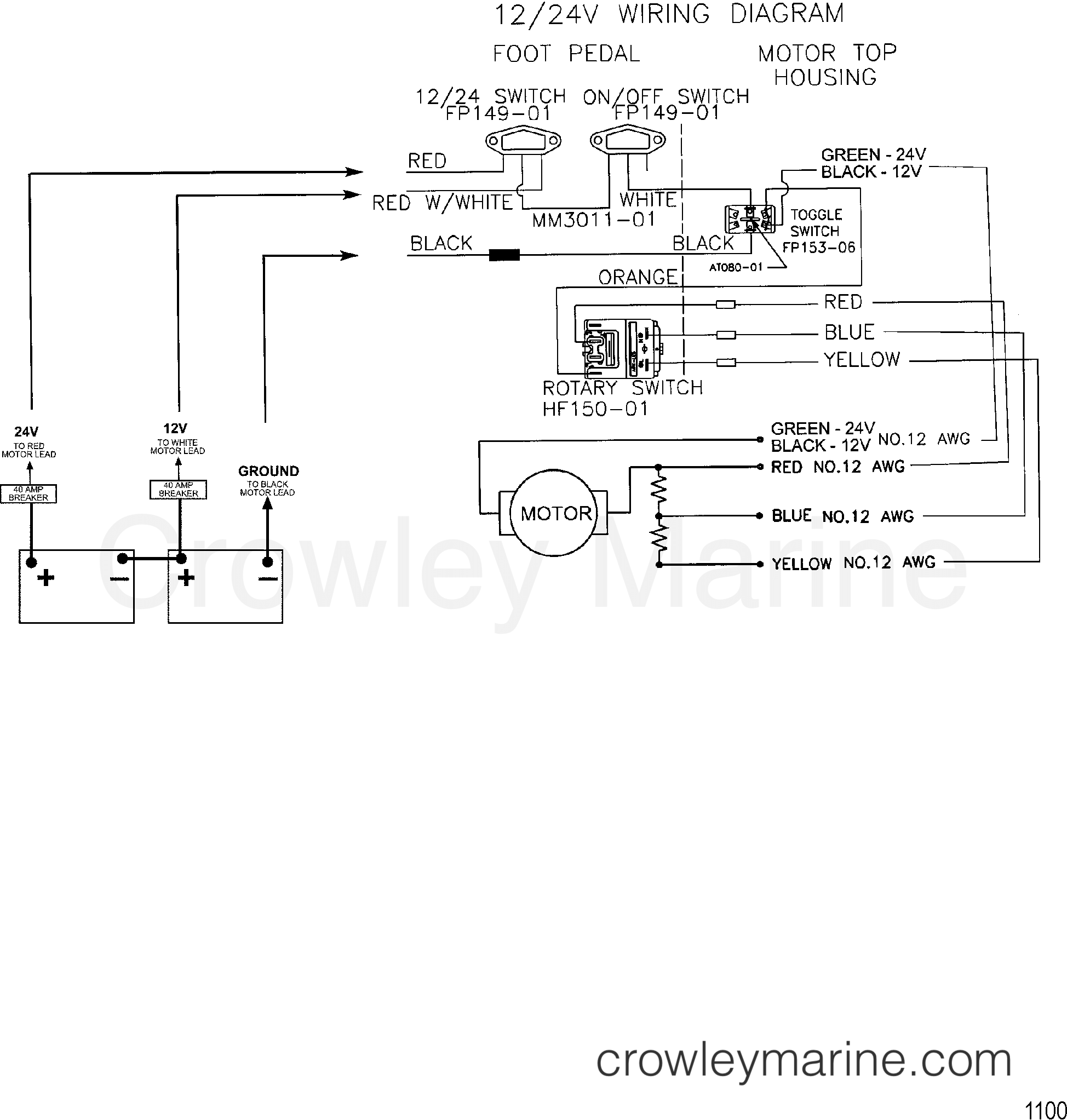
WIRE DIAGRAM(MODEL 667) (24 VOLT) - 1999 Electric Trolling Motor 12/24V

Various controlled dc loads connected to the 270-VDC bus in the VSCF
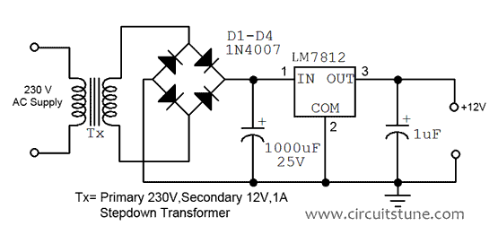
12v Regulated Power Supply Circuit Diagram | CircuitsTune

Kti Hydraulic Pump Wiring Diagram - Wiring Diagram